![]() Estimating Edge’s team of experienced construction professionals and software engineers have developed the industry’s smartest takeoff and estimating software solutions for competitive estimates.
Estimating Edge’s team of experienced construction professionals and software engineers have developed the industry’s smartest takeoff and estimating software solutions for competitive estimates.
Don’t just estimate faster. Estimate better.®
- /
- /
- /
- /
- /
Standing Seam Condition Document (v12)
The Standing Seam Condition provides estimators with specific calculations to improve the accuracy of their standing seam roof estimates. This document will cover the following:
- Setting up the Standing Seam Condition properties
- Utilizing Take-Off features designed for the Standing Seam Condition
- Hip Locate
- Hi-Lo
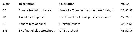
- Standing Seam Condition Quantities “CQty’s” and how they are calculated
- Standing Seam Layout Report
- Standing Seam Panel Waste at Hips or Valleys
- Known limitations
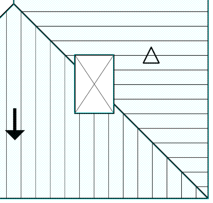
Displays the roof section measured for the calculations used in this document.
For this example, we are using a panel that is 18” wide and has a stretchout of 24”.
Residential Standing Seam Roof

- Setting up the Standing Seam Condition properties
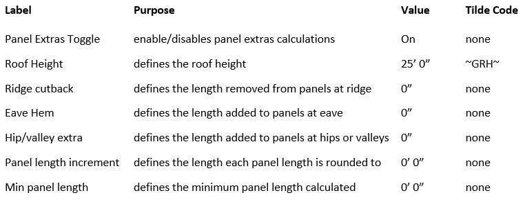
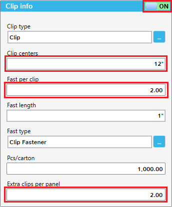
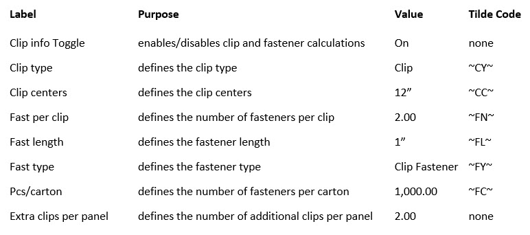
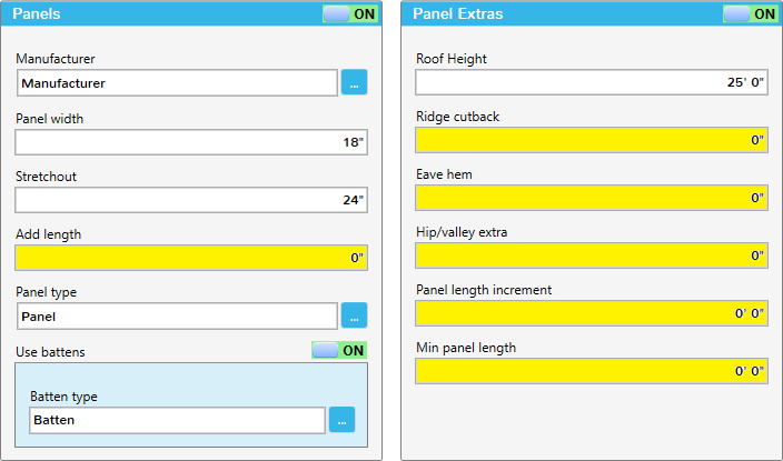
The images below display the sections of fields and On/Off Toggles on the General Tab of The Standing Seam Condition. This is where the estimator will define the properties that will directly affect Standing Seam specific CQty’s. The highlighted fields assist with CQty calculations. The others are available to populate item descriptions. The fields that have corresponding Tilde Codes are noted below the images.
Panels Section


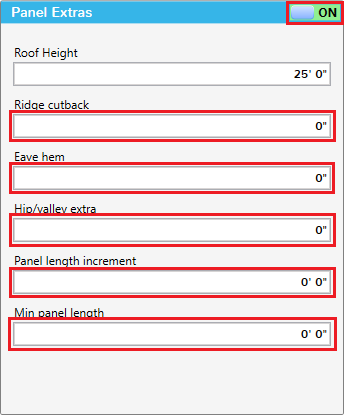
Panel Extras Section
Clip Info Section
- Utilizing Take-Off features designed for the Standing Seam Condition
A. Hip Locate
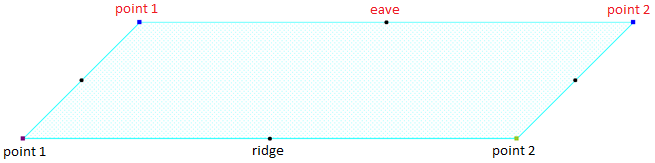
The Hip locate tool assists the estimator with choosing the appropriate starting points when digitizing sloped roof sections. Since the panel layout begins at the starting point, if you use the same starting point to measure adjacent roof sections, you can ensure that your panel seams will line up along hips, valleys and ridges. The process requires three digitized points. For this example, I will digitize two corners of the roof and then digitize a point in the field area. The locate points are placed based on the points digitized and the panel width, which in this example is 18”.
To use the Hip locate tool, start by clicking on the tool bar button ![]()
-
-
- digitize point 1
- digitize point 2
- digitize point 3 anywhere in the field on the roof
-
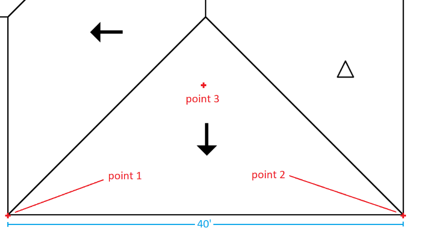
The distance between point 1 and point 2 is the basis for all locate points. Point 3 only specifies on which side of the line between points 1 and 2 the locate points will be placed (in this example, above or below).
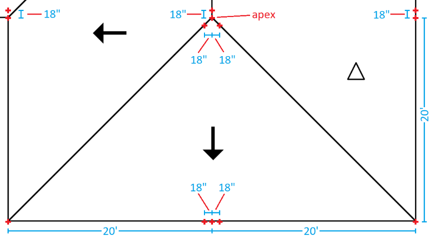
There are 13 locate points in total:
-
-
- Two locate points are placed on points 1 and 2, the exact points that were digitized with the Hip locate tool.
- Three locate points are placed halfway between points 1 and 2. The midpoint lines up with the apex, the 2 outer points are spaced 18” (panel width) from the midpoint.
- Four locate points are placed at the apex. One is placed on the apex, the other three are placed 18” from the apex, along the ridge and hips.
- The last four points are placed 20’ (half the distance between points 1 and 2) from the original points 1 and 2, and then 18” from them.
-
-
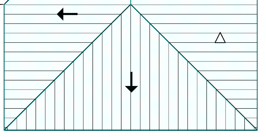
- If the estimator digitizes all three sloped sections starting at the apex, the panel seams will line up along the hips and ridge. (See Example 1 below).
-
- If the estimator wanted the panels centered on the ridge, they would choose a starting point at the apex, but not on the apex. (See Example 2 below).
Example 1
Example 2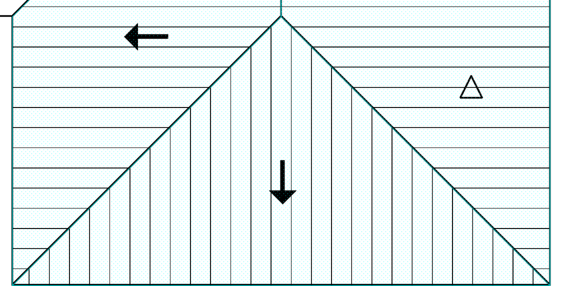
General Information: Panel placement begins at the starting point (the first point digitized when measuring roof area). If an estimator does not like the layout that displays on the Take-Off screen after defining hi-lo, they would have to delete the shape and re-digitize it from a different starting point. The Hip locate tool was designed to assist estimators with their layout.
B. Hi-Lo
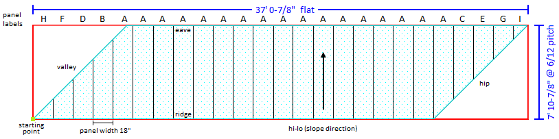
The Hi-Lo tool defines the slope direction of the roof section and directly affects the panel length calculations, because panel layout calculates based the following criteria; starting point, area measured and direction of hi-lo. The EDGE takes the unpitched length of each shape perpendicular to the hi-lo (37’ 0-7/8”) and divides it by panel width (18”)
You can choose from three Hi-Lo Configurations.
-
-
-
- Two-point Hi-Lo
- Three-point Hi-Lo (points 1 and 2 would be digitized at the eave)
- Three-point Hi-Lo (points 1 and 2 would be digitized at the ridge)
-
-
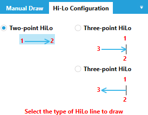
Use the default Two-point Hi-Lo if you can draw the Hi-Lo line in Ortho Mode, i.e. at a 45-degree angle.
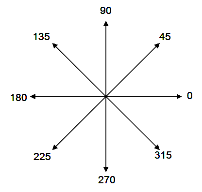
Example of angles that can be digitized in Ortho Mode.
Use either Three-point Hi-Lo option when you need to use the ridge or eave as your base line.
To define a Hi-Lo for an area, first select the area and then click on the tool bar button ![]()
-
-
-
-
- digitize point 1
- digitize point 2 (stop here if using Two-point Hi-Lo)
- digitize point 3 anywhere in the field of the roof (this step is only required for Three-point Hi-Lo)
- If your panel layout doesn’t look correct, re-digitize the Hi-Lo.
-
-
-
Roof area before Hi-Lo designation
Roof area after Hi-Lo designation


For other CQty’s not listed, please refer to BUR Area Condition Document (Insulation Tab)
-
-
- Standing Seam Condition Quantities “CQty’s” and how they are calculated (continued).
-


-
-
- Standing Seam Layout Report
-
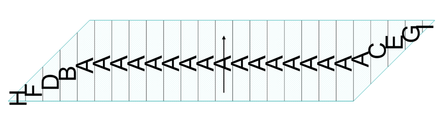
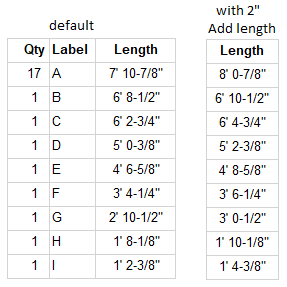
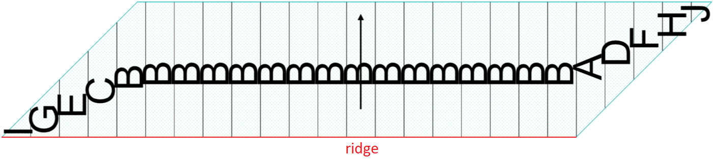
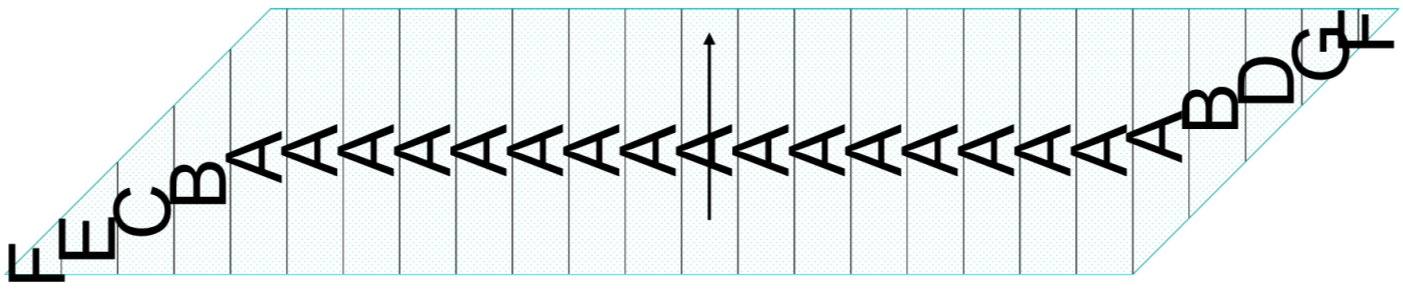
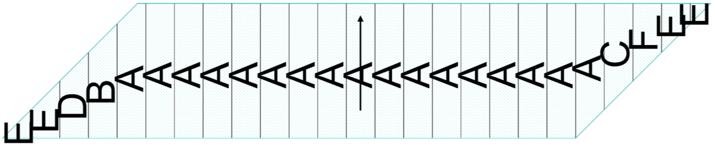
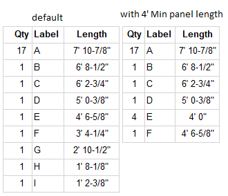
Page 2 of the Standing Seam Report displays the quantity of each panel as well as its label designation and length.

Estimators can tweak panel length calculations by modifying any of the highlighted fields.
Add length: Length added to every panel. If the estimator types 2” in this field, each panel length would increase by 2”.
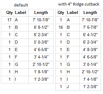
Ridge cutback: Length removed from every panel along the ridge. If the estimator types 4” in this field, the panels along the ridge would be 4” shorter. The ridge is colored red for this example, panels not affected: A, D, F, H, J
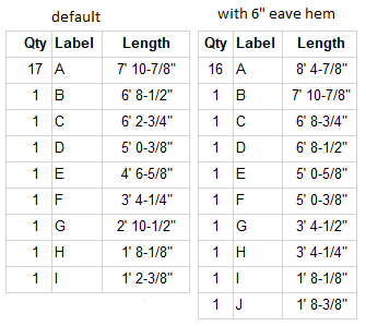
Eave hem: Length added to every panel along the eave. If the estimator types 6” in this field, the panels along the eave would be 6” longer. The eave is colored red for this example, panels not affected: I, H, F, D, B

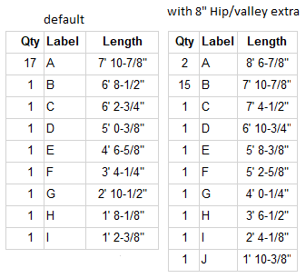
Hip/valley extra: Length added to every panel along the hips or valleys. If the estimator types 8” in this field, the panels along hips or valleys would be 8” longer. The hip and valley are colored red for this example, panels not affected: B

Panel length increment: Amount each panel length is rounded. If the estimator typed 1’ in this field, each panel length would round up to the nearest foot.
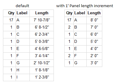
Min panel length: Defines the minimum panel length calculated. Panels would have to be cut to the appropriate length in the field. If the estimator typed 4’ in this field, no panel length would be less than 4’. Panels affected from default layout: F, G, H, I were rounded up to 4’ 0” and consolidated into Panel E. The original Panel E is now designated as Panel F.
The purpose of these examples is to display the affect each field can have individually. Estimators will typically use a combination of these fields rather than just one.
-
-
- Standing Seam Panel Waste at Hips or Valleys

- Standing Seam Panel Waste at Hips or Valleys
-
The above image illustrates the waste calculation along the hip of the sample roof section. Valley waste calculates similarly.
-
-
- Known Limitations
-
The Standing Seam Condition is an Area Condition so it has the standard measuring tools associated with all Area Conditions:
Area ![]()
Deduct![]()
If a deduct is digitized across two areas, it will calculate additional panels inside the deduct, resulting in inaccurate quantities.

To get the proper result, while digitizing each area, digitize around the object.