![]() Estimating Edge’s team of experienced construction professionals and software engineers have developed the industry’s smartest takeoff and estimating software solutions for competitive estimates.
Estimating Edge’s team of experienced construction professionals and software engineers have developed the industry’s smartest takeoff and estimating software solutions for competitive estimates.
Don’t just estimate faster. Estimate better.®
- /
- /
- /
Manual Draw
How To Use Manual Draw
Overview:
There are three ways in which one can draw objects in The EDGE, they are:
1. Digitize from paper blueprints
2. Digitize from electronic blueprints
3. Manual Draw
Manual Draw comes in handy when you are handed a field sketch or a fax drawing to estimate into a job. This may seem to be an intimidating task if you are not using The EDGE. With The EDGE you can quickly convert a field sketch or fax drawing to a scaled drawing/estimate. Manual Draw allows you to draw lines from a point at an exact length with minimal effort. Manual Draw only has a few simple rules to follow and it is extremely easy to learn and use, a quick tutorial follows.
Manual Draw Rules
– In order to draw using Manual Draw in The Edge you must be in either Area or Length
– You always need a starting point by touching your mouse or digitizer pen/stylus someplace on the digitizer board
How Manual Draw Works
1. You start a job, create a scale, loaded your conditions and opened the Drawing screen.
2. You have clicked on the Area icon with your mouse.
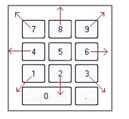
3. You have established a starting point by clicking your mouse somewhere in the active area of the digitizer board. The best way to pick a starting point is to look at your field sketch. Orient the longest direction horizontally and pick a point about 16″ in from the left side of the board and about 12″ up from the bottom of the board. You can now put your mouse down, you will not need it again until after the drawing in finished. Look at the two figures below. They are cutouts from a typical keyboard, the left is an example of the directional arrows and the right an example of the numeric keypad.

We will now draw a rectangle using the directional arrows.
4. Hold down the Control (Ctrl) key and press the right arrow key and type 200 in the Length field, click OK.
5. Hold down the Control (Ctrl) key and press the up arrow key and type 100 in the Length field, click OK.
6. Hold down the Control (Ctrl) key and press the left arrow key and type 200 in the Length field, click OK.
7. Hold down the Control (Ctrl) key and press the down arrow key and type 100 in the Length field, click OK.
8 . The same thing can be accomplished using the Numeric keypad arrow keys.
A. Hold down the Control (Ctrl) key and press the number 6 key and type 200 in the Length field, click OK
B. Hold down the Control (Ctrl) key and press the number 8 key and type 100 in the Length field, click OK
C. Hold down the Control (Ctrl) key and press the number 4 key and type 200 in the Length field, click OK
D. Hold down the Control (Ctrl) key and press the number 2 key and type 100 in the Length field, click OK
How To Use Manual Draw
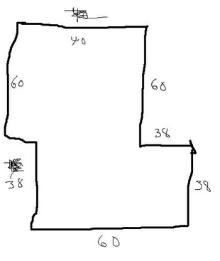
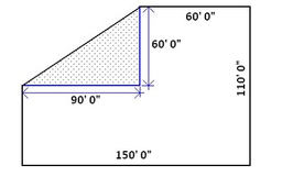
You have been handed the field sketch below. How do you get this into The EDGE and generate a scaled drawing and a quality estimate? Use Manual Draw to replicate the field sketch and from there proceed as you normally would.
1. Start a new test job, you will need to create a Page and on the Condition screen bring in a group as you normally would. Set the Page Scale to ¼” = 1’ 0”.
Note:
When creating the Page you normally enter the scale of the plan you are working from. In this case there is no scale. Take a look at the field sketch. This is not a large build ¼” = 1’0” will probably work, if the building was larger try 1/8” scale. Just pick a nominal scale.
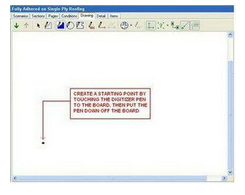
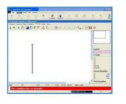
2. Move to the EDGE Drawing screen. To begin to draw manually take your stylus or pen and touch down on your digitizer board. This point will be your Starting point. Once you have established the starting point put the pen down, you won’t need it again.
Note:
Look at your sketch for a moment. There is a small jog on the left side of the building that is not dimensioned. In a case like this the best thing to do is to start at one end of the missing dimension and finish at the other end of the missing dimension.
To draw you have two options:
– Use the dedicated arrow keys on your keyboard.
– Use the arrow keys on the numeric keyboard.

In the above picture you see the arrow keys circled and the numeric keypad arrows circled individually. Also note the Control (Ctrl) key has been circled as well
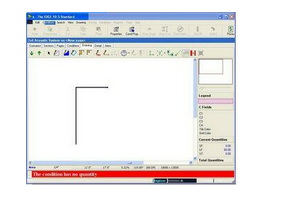
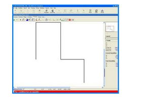
3. Hold down the Control key and press the Up Arrow (Ctrl+↑). Or Hold down the Control key and press the number 8 on the numeric keyboard (Ctrl+8).
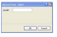
– The Manual Draw – Up window opens.
– Type 60 and click OK
4 . Hold down the Control key and press the Right Arrow (Ctrl+→). Or Hold down the Control key and press the number 6 on the numeric keyboard (Ctrl+6).
– The Manual Draw – Up window opens.
– Type 40 and click OK
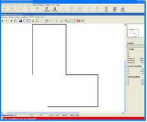
5. Hold down the Control key and press the Down Arrow (Ctrl+↓). Or Hold down the Control key and press the number 2 on the numeric keyboard (Ctrl+2).
– The Manual Draw – Down window opens.
– Type 60 and click OK
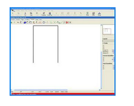
6. Hold down the Control key and press the Right Arrow (Ctrl+→). Or Hold down the Control key and press the number 6 on the keyboard (Ctrl+6).
– The Manual Draw – Up window opens.
– Type 60 and click OK.
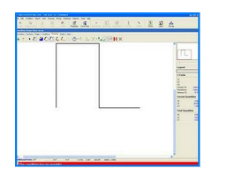
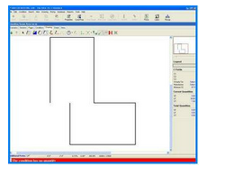
7 . Hold down the Control key and press the Down Arrow (Ctrl+↓). Or Hold down the Control key and press the number 2 on the numeric keyboard (Ctrl+2).
– The Manual Draw – Down window opens.
– Type 38 and click OK
8 . Hold down the Control key and press the Left Arrow (Ctrl+←). Or Hold down the Control key and press the number 4 on the numeric keyboard (Ctrl+2).
– The Manual Draw – Left window opens.
– Type 60 and click OK
9. Hold down the Control key and press the Up Arrow (Ctrl+↑). Or Hold down the Control key and press the number 8 on the numeric keyboard (Ctrl+2).
– The Manual Draw – Up window opens.
– Type 38 and click OK.
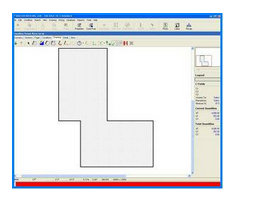
Take a moment and look at the “field sketch” we have been using to create this building. In typical fashion we forgot or omitted one dimension; in our situation it happens to be the dimension needed to ‘close’ the building. You have a few choices
– You could go back to the job site and measure the missing dimension.
– If you trust your other dimensions, you can merely press Enter on your keyboard. Since you are measuring in Area, area has to ‘close’ itself in order to be able to calculate area. Pressing Enter will always draw a line from the last point digitized to the first point digitize.
10. Press Enter
Advanced Manual Draw Techniques
The EDGE also incorporates some advanced drawing features in the Manual Draw program. So far on the numeric key pad you have used the 2, 4, 8 and 6 keys. The 1, 7, 9 and 3 keys are available for drawing angles or for entering up and over measurements.
The arrows represent the direction the key when used in conjunction with the control will draw a line.
When you use the keyboard to start manual draw one of the following windows will open.

These manual draw dialog boxes are different than the ones used for right, left, up or down arrow keys. You have two choices here
– You can simply enter the length of the line to be drawn and click OK. That line will be drawn at a 45° angle corresponding to the dialog box tile or as depicted in the keyboard sketch above. This works well for building that have angles of 45°
– For those buildings where the angle cannot be easily determined, you can use the up and over method. Here, you measure the length of the base and the length of the height. Put those measurements on your field sketch such as below.
The EDGE will then draw the hypotenuse.
To familiarize you with this feature start with a clean drawing screen and try this example:
1. Make sure Area is selected.
2. Touch your digitizer pen to the board, this should initiate a Starting Point, put your pen down.
3. Press Ctrl+1 and enter 100 in Length line, click OK
4. Press Ctrl+7 and enter 100 in the Length line, click OK
5. Press Ctrl+9 and enter 100 in the Length line, click OK
6. Press Ctrl+3 and enter 100 in the Length line, click OK

So far we have looked at Ctrl + 2, 4, 8, or 6 and Ctrl + 1, 7, 9, and 3. There is still one more manual draw key Ctrl+5
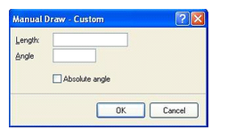
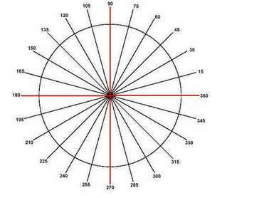
Here, the EDGE allows the user to enter a length and a custom angle (in degrees). Try the following experiment:
1. Using the same drawing screen as before take your pen and touch the board to the left or right of the square you just drew.
2. Put the pen down.
3. Press Ctrl+5.
4. In the Length field type 40.
5. In the Angle field type 45, do not check the Absolute Angle box.
6. Click OK.
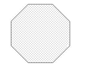
7. Repeat steps 4, 5 and 6 seven (7) more times, when finished you should have a drawing similar to the one to the right
Now find another blank area on your drawing screen. Touch your pen to the digitizer and create a third Starting Point. Put your pen down and:
1. Repeat steps 3, 4, 5, 6 and 7 but this time check the Absolute Angle check box.
2. Repeat step 7 three (3) times, making sure you check Absolute Angle each time. Look how the lines are drawn; it draws the line in the same direction. See below.
Using Absolute angle draws line in the direction shown below in degrees.